I. Introduction
The scope of this project was to obtain tangible efficiency turbines through mass balance water input and output by the deployment of flow rate sensor from various point measurement inlet and outlet at Water Treatment Plant for Power plant (Coal). The application was for monitoring only. No control sequence or safety shutdown system involves.
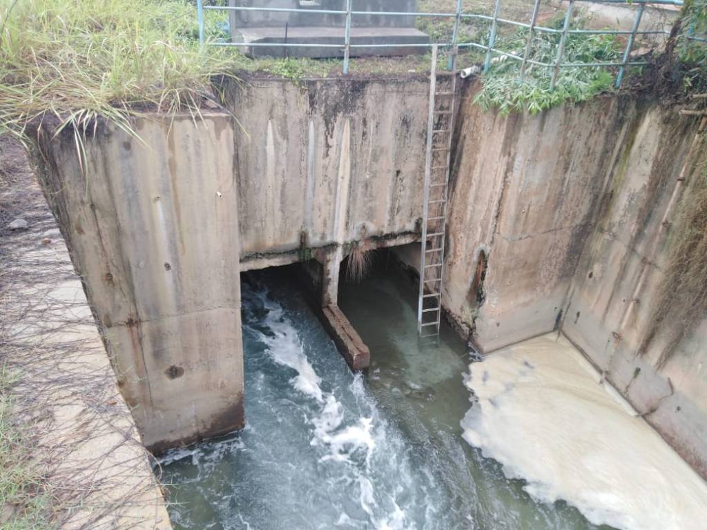
Among these flowmeters, a specific case that drains our attention. It was solving the open channel flowmeter on the outfall unit from the condenser. The water cycle operation is never expected to shutdown, either 2 x 50% or 2 x 100% operation of power generation. This situation contributes to the complexity of hydraulic structure/weir installation.
An open channel flow meter is not frequently part of the scope project not many as flow meter carried in closed conduits that flow completely the piping system. In this article, I would walk you through to capture the problem encounter during the installation hydraulic structure of open channel flow meter. In the end, it will influence the selection sensor for open channel flowmeter to enable the installation and to eliminate the possibility of failure.
Weir, as seen in the construction design, is essentially a dam built across an open channel over which the liquid flows. It simple based on the design especially when selecting rectangular weir without end constructions. I overlooked the weir thickness requirement and installation method. The installation method is so crucial in order to place the weir as a hydraulic structure.
The requirement thickness should be calculated by a structural engineer in regard to force exerted on the weir. Moreover, the installation method should review by construction engineer since the water flow could not be stopped, only in certain circumstances, the water flow will undergo low flow rate.
The other difficulties factor is we don’t have structure or installation engineer, so we fully trust the responsible for structural and installation scope to the contractor. It was not all the contractor’s mistake since we didn’t request any calculation and installation procedure document.
All the explanation below is related to the projects.
II. PLC and HMI
I was in-charge for programming, designing, and configuring both Programmable Logic Controller (PLC) and Human Machine Interface (HMI). Although there is A comprehensive guide selection of PLC is available in relevant details such as IEC 61131-1 and IEC 61131-2.
In common practice especially for PLC package in an existing plant, PLC is selected based on, as follows:
- Hazard and operability study (HAZOP) to identify the requirement of safety integrity level for the PLC
- The capability to cope the application.
- Project budget.
- Certain population PLC on the User/Company premises.
- Service availability PLC product on the country.
In this project, the PLC selection was toward to no.4 besides the project budget. It was agreed to use PLC Simatic S7-1200 CPU 1214C. S7-1200 is sufficient for the specified application. The main application was to monitor flowrates on different locations at demineralize water systems. There is no control and safety requirement for the shutdown process.
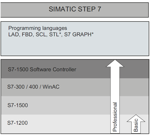
Nowadays, PLC developer is competing to create integrated automation software with one engineering environment and one software project for all automation tasks. Siemens has built an integrated software portal named as TIA portal. This is a Control Engineering 2012 Engineers’ Choice award winner. As a user I admit, it was really convenient and easy using Step 7 professional and RT advance. However if you are a new learner, it is recommended to read the guideline to familiar the program blocks. Selection engineering software depends on the controller model. Actually, STEP 7 Basic is sufficient. However, since the plant has various Siemens controllers into it is decided to use STEP 7 Professional.
Whether it’s the inexperienced or experienced writing the PLC program, simple ladder logic, and a step sequence is often the best solution. It was developed using ladder logic and function block diagram, Step 7 utilize grouping the ladder logic name as a network.
After deciding the PLC brand, there are several factors to be considered such as.
- Power supply quality
- PLC Program
- Signal transmission
- Conformance to Hazardous Area
II.1 Power Supply Quality
AC voltage is the main source power, vendors provide module AC to DC with various power wattage. Each power module will supply PLC rack. It will power the I/O module either through the back plane or cables. Most cases, field instrument is using dedicated AC to DC power supply. Power supply quality is important for a steady condition for the I/O module either analogue or digital module.
It should carefully evaluate when PLC power supply is the same source with an inductive load such as a motor. Power quality should be one of the considerations when utilizing 4-20mA analogue input. Power quality refers to the ability of electrical equipment to consume the energy being supplied to it. A number of power quality issues including electrical harmonics, poor power factor, voltage instability and imbalance impact on the efficiency of electrical equipment. Equipment instability and failure.
Below is a simplified interconnection diagram, one of example when power quality could interfere 4-20 mA signal and flickering digital signal. The symptoms analogue fluctuation and flickering always occur whenever the density sensor connected to the AI Module.
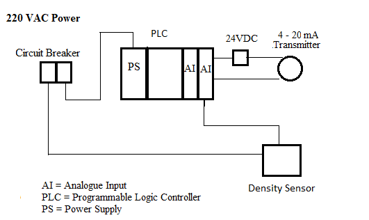
At first sight, we suspect it comes from inductance coupling between cable AC and analogue, digital wiring (24VDC). Although the arrangement cable inside the cabinet has been separated between AC and 24VDC. The distance is adequate to minimize inductance coupling using a cabinet with a width of 800 mm.
We also suspect from grounding issues. We have to provide proper grounding for the power supply PLC and power supply converter 220VAC to 24VDC. Since not all companies segregate between instrument grounding and power grounding only equipment with source 220VAC is connected to dispatch grounding.
In the end, we figure out that the problems are caused by power quality due to harmonics. So we decided to use AC to AC converter. It solves the problem.
II.3 PLC Program
PLC program of this project consists of:
- Scaling complete with simulation input
- Alarm (High only, High-high provides but not use since no emergency action applied for flowrate)
- Totalizer
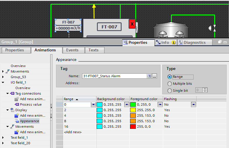
This program is a standard basis for a flowmeter. The scaling and alarm function block could be combined (as seen in figure 1). The function block is created by user from the basic function block.
Not all user function block requires developing from scratch. Siemens has provided additional add-on libraries available on their website. One of the examples is Totalizer.

II.3.1 Memory Capacity
The size of memory capacity depends on several factors even the style of programming could affect memory capacity. Deciding memory capacity is vital when the plant is continuously extended or expanded.
The other factor of memory capacity as following:
- The number of input-output, number of variables, constant, and contribute to consume memory IO.
- System architecture with other devices.
- The individual style programming and programming language.
- The Complexity of the application. Scaling, mapping, and alarm are typical or standard program. One of the examples complexity programs could be is represented in the control loop method. Feedforward, Close loop, 2 degrees of freedom control etc.
II.3.2 Scaling 4-20mA to Engineering Unit
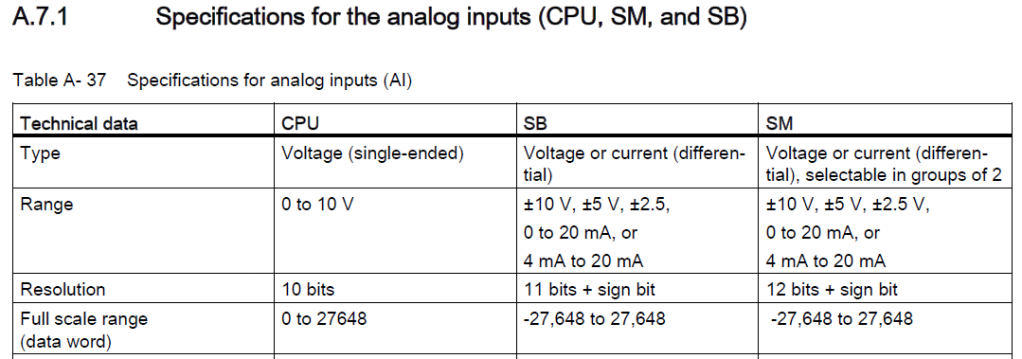
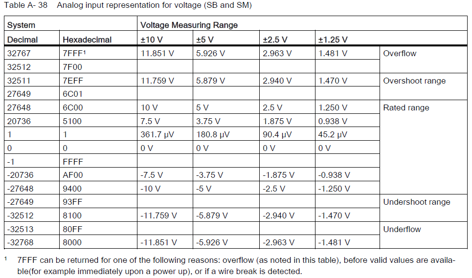
Raw value as a representation of 4-20mA could have a different minimum or maximum value among the modules. The value to be determined based on the function purpose. Below are different full-scale ranges among the module.
The engineering unit scale between PLC and transmitters should be the same. Thus, a linearity relation between 4-20 mA and the engineering unit is created. 4 mA as lower range value and 20 mA as upper range value.
However, you need to decide the unit and scale to be sent from the transmitter.
In the example of a Magnetic flow transmitter, the information conveyed in 4-20mA could be presented in either velocity or flowrate. If you choose a velocity, in consequence, the flowrate equation should be created in PLC program.,
If the engineering unit scale between PLC and flow transmitter is different the linearity between the devices will be different. In addition, errors contribute to non-linearity. There is four error that contributes
- Zero Error
- Span Error
- Linearity Error
- And the combination above
In case this happens, the display in the transmitter and HMI will be different.
II.3.3 Totalizer
Totalizer is used to determine the accumulative flowrate during a certain period. For example, “in the last 60 seconds, there have been 30 gallons of water flowing by the sensor.”
To obtain consistency accumulation during certain periodes, Totalizer should be considered as an interrupt. Thus regardless of the complexity of the program. It would give high priority to maintain a consistency time period.
One you should aware of when implementing Totalizer in the PLC program. The raw value should be limited for instance 0 to 27648. Over and under this value, it should be identified as an error. The error should not consider as a value in totalizer. It should hold totalizer or give input value 0 on the totalizer function block. Over and under range, the value could be used to identify short or loose cable wiring.
II.4 Signal Transmission
Selecting signal transmission to convey the information Besides conventional 4-20mA, the other option is to use HART. HART protocol offers a number of advantage however there are drawback should be considered.
Much technical literature is available to explain HART protocol in detail. The compatibility between HART and 4-20 mA wiring. Field transmitter complete feature HART enables to ease of calibration system.
Several advantage when using HART Protocol as following :
- Not necessary to provide scaling analogue function block
- Totalizer is not requiring defining the PLC program. Totalizer is available on certain field instruments. PLC will send a command to start and stop the Totalizer.
- Besides the primary variable, the other parameter could be obtained. Other parameter known as a secondary variable, tertiary variable This variable could retrieve by three classes of HART commands:
- Universal commands
- Common Practice commands
- Device-Specific commands
- If there were concerns about hazardous areas, HART protocol is claimed to be more intrinsically safe.
Therefore, it is depicted that HART has an advantage over conventional 4-20mA. There are several things to be considered in order to use HART
- Do they possess Asset Management
- SystemCPU (processing unit) and AI cards should be compatible. For Siemens PLC, HART is using ET200. This series is far compared to the S7-1200 series
- Version to be check
- Selection of cabling system – Peer to peer or multi-drop.
- Installing or enabling resistor 250 ohm. Scaling is not required even you could retrieve 3 data parameter simultaneously named as
- PV; Primary Variable
- SV; Secondary Variable
- TV; Tertier Variable
II.5 Hazardous Area
Mostly, PLC is located in a safe area i.e. technical room, meanwhile, the field transmitter is located in a hazardous area. Hazardous area certification for field transmitters should be inline with the wiring. When using conventional 4-20mA, the wiring in the hazardous area needs to be check. Mostly, when the PLC and the field transmitter have different hazardous areas.
III. HMI
Human Machine Interface is a user interface or dashboard that connects a person to a machine, system, or device. It is stand-alone and independent from the existing DCS system.
The selection of HMI is based on the architecture of the application. The architecture of HMI/SCADA will determine the license to be purchased. There is more detail, for selection HMIa . Below are several overviews
- Independent/Stand Alone. The license either development or runtime license.
- SCADA Based, If SCADA is selected next it to decide the sharing data., DDE Server, OPC or combination
- SCADA based definitely require development license
- Web client
This project is using Wincc RT Advance

There is an option based on feature and scale-able of
- Basic
- Comfort
- Advanced
- Professional
The reason to deploy Wincc RT Advance it has minimum features to covers the flowmeter application. In general, the HMI consist of
- Representation displays such as P&ID. Symbol and coloring mostly based on the industries. The company could also produce specification and regulation for symbol and coloring
- Alarm management, it will be guided through ISA. Alarm animation is important for operator to identify situation.
- Inhibit
- Logging, (logging of process values and alarms). Please be aware logging Options for WinCC runtime Advance
- Trending, Individual trending each flow transmitter
III.1. General Alarm
General Alarm has different tone for specifics events. Indeed, it is different between Company. To notify all attendant in the plant. Each area is equipped with annunciation.
This project didn’t integrate with existing General Alarm
III.2 Alarm
In industries where process hazard analysis results in minimum SIL 2. It requires 2 systems separated. Process Control System and Safety shutdown system.
When these systems exist. Grouping occurrence of alarm based on the system. PCS covers high and low alarm while SSS generate alarm High-high and Low-low. High-high and low-low alarm have consequence action to the process closing the valve or stopping the pump.
As stated, this application only for monitoring there is an alarm rule that could be waived. No intervention by maintenance personnel is required. High-high and a low-low alarm is not mandatory thus reset alarm through acknowledge is not mandatory either. The alarm logging is available.
The other feature does not require are
- Maintenance inhibit
- Start-up Inhibit
III.2.2 Alarm Animation WinCC
Alarm animation is important for an operator to know the condition of the plant. Usually, each company has different specifications for color and shape to animate the process plant.
It could be similar to the same type of business or industries.
I found that the way to represent alarm animation assign to a variable on WinCC advance is kindly different from other software HMI. Usually, the shape contains 2 tags or 1 structure tag.
Usually, I use structure to group alarm for one tag i.e.
- PT001.HH with set point 90% of the maximum range
- PT00.HH with set point 70% of the maximum range
- PT001.L with set point 30% of the maximum range
- PT001.LL with set point 10% of the maximum range
The other way is to generate dedicated variable i.e
- PAH001
- PAL001
The alarm is discrete 1 or 0; True or False. Meanwhile RT Advance uses integer value to generate different level alarms. The way to generate an alarm on RT advance is kindly different from what I use on other HMI. RT Advance use integer value to generate different level alarms
Faceplate
A faceplate is a configured group of displays and operator objects. The “data exchange” with the display and operator objects contained in the faceplate is performed via an interface at the created faceplate.
The properties of the used display and operator objects are assigned to the individual objects in the “faceplate editor”. Faceplates can be managed and modified in a central library.
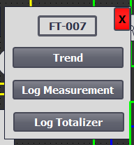
This project use faceplate as seen below. No control applied on the faceplate. No universal standard for a faceplate. It is custom depends on the application. In this project, the faceplate consists of
- Individual trend flowmeters
- Individual log measurement
- Individual totalizer
IV. FLOW TRANSMITTER
All flowmeter is connected to the new dedicated PLC and HMI. It is stand-alone and independent from the existing DCS system.
In a standard basis, selecting flowmeters usually based on the
- Accuracy requirement (for fiscal service or not)
- Type of fluid and other fluid parameters
- Installation constraint. Equipment that can be reached for inspection, repair, or monitoring from permanent platforms is more likely to be inspected, calibrated, and replaced than equipment that requires climbing with a safety harness or scaffold.
There were 3 types of flowmeters used in this project
- Vortex flowmeters, operate under the vortex shedding principle, where an oscillating vortexes occur when a fluid such as water flow past a bluff (as opposed to streamlined) body. Vortex mostly uses in application of steam.
- Magnetic flowmeters, this type of flowmeter is very common for water service due to the dominant conductivity parameter.
- The ultrasonic flowmeter as a secondary device. The ultrasonic level meter is not only used for the level meter but it could use as a parameter to determine flowrate of open channel water. The equation will be embedded in the PLC program. For this application, it implements for the open channel consist of culverts and open channel.
Each flowmeter has a different method to obtain the flowmeter value. Each will have a different equation.
In the case of open channel flowmeter, there are several methods. The primary device for ultrasonic flowmeters are:
- Weirs
- Flumes such as Parshall flumes, Cutthroat Flume
IV.1 Rectangular Weir
In the first design, we use rectangular weir for the simplicity design
Flow rate equation based weir method, Q = 6620(L-02.H)H1.5,
Where :
Q = flowrate
H = head on the weir
L = crest length of weir
K = constant dependent upon units
IV.2 Cutthroat flume
There is a similar method as Parshall flume named as a cutthroat flume. In this project, the cutthroat flume is applied to measure flowrate at sewerage as a primary device.

W=KW1.025Han = CHan
Q=free flow rate(cfs / m3/s)
K=flume discharge constant (varies by flume length/units)
C=flume discharge constant (varies by flume length/throat width / units)
W=throat width
Ha = depth at the point of measurement (feet / meters)
n = discharge exponent (depends upon throat width)
The constant flowrate equation Parshall flume is determined by the selection range of flowrate and the dimension of open channel. More detail is available in the link below
https://www.openchannelflow.com/flumes/cutthroat-flumes
There are two ways to obtain flowrate using ultrasonic. In reality ultrasonic only measures the height. The flowrate equation could be configured either in the ultrasonic transmitter or PLC.

IV.1.1 Selection of 4 wire or 2 wire transmitter
The selection 4 wire or 2 wire transmitter is the intention of the user and evaluation actual condition. These transmitters are called “4-wire” or self-powered. The current signal from the transmitter connects to the process variable input terminals of the controller to complete the loop.
Mostly the reason to use 4 wire as follows:
- PLC is not available as acquisition data. The transmitter should have displayed on the transmitter so measurement is readable
- Three and four-wire devices incorporate an external power supply in order to effectively eliminate the voltage drop placed on the processed signal current loop
- Some device is not available as 2-wire. Some sensor requires external power to drive the chemical/mechanical event in the transducer.
V. INSTALLATION
The initial design was proposed using Parshall flume, the idea was to avoid high force when the maximum flow rate through the primary device. However, the member team decided to use weir for the simplicity of the design. It was understandably the main concern of the project team, Parshall flume is not easy to construct. In addition, there were no local vendors able to precast the Parshall flume.
We decide to use Weir to measure the water meter outflow unit. As a reference, I use Flow Measurement Practical Guides for Measurement and Control Handbook published by ISA.
Weir are the simplest, least expensive, and probably most common type of the primary measuring device used to measure flow in open channels.
After sizing the weir, I don’t pay attention to the installation procedure. There are two rectangular channels. The water flow never stops flowing. The only possible scheme is to place it down during the low water flow. Since it is using concrete, I thought with this weight it will easily dip into the water. Moreover, construction and installation are responsible to the contractor. If the contractor confirms they could install it then it became their responsibility. As a team, we really don’t concern about this until the installation start.
The installation method for the primary device for open water is really critical. It is even more important than sizing. If the installation seems impossible then quickly turn to use other methods.
High water flow is a detriment to the weir or Parshall flume structure.
Since we don’t have a data flowrate outlet, the sensing range flowrate only through observation. I was not sure the water flows were in low or normal flowrate, but it is convincing that it would not disrupt the process when laying down the weir structure using a crane.
It is not as expected, when the weir structure dipped into the water as it water tip the bottom weir structure, the hoist cable start swing. The degree hoist cable swing becomes bigger when the weir dipped deeper to water until the crane start to lift from the ground. The installations stops and not continue.
Basically there are two option solution from my knowledge
- To find a way for a better method of installation. However, there still a risk if the installation fails again. Moreover, the remaining project budget reveals that there is no room for failing.
- Change the flowrate measurement method with an admissible installation scheme.
After gathering information, the most reasonable is option 2. It automatically changes the equation to
Q = A x v
A = surface area
V = velocities
A = length x width where length is similar to height (H). Height(H) will be determined using the ultrasonic sensor. The width of channel is 2 mtr.
Now to determine the method velocity.
The first option is using the non-contact method
Non-Contact Sensor
The velocity could be measured using ultrasonic or laser. Laser velocimeter has a laser diode to determine the stream’s level by emitting an ultrasonic pulse and measuring the time it takes for the an echo to return for the stream’s surface. The transducer is both a pulse transmitter and an echo receiver. Certain manufacturers already provide integrated between velocity sensor and level sensor. Since the ultrasonic is measuring the level. The remaining sensor is the velocity
It could be installed on the surface. Since the flow much turbulence it is and a lot of ripple on the surface. We consult to the vendor, their recommendation is to
Contact Sensor
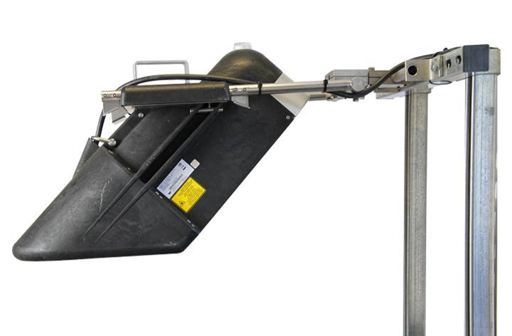
The Second method contact by immersing the sensor
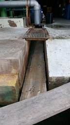
The other could be installed inside the water. The sensor is installed at the bottom of the channel.
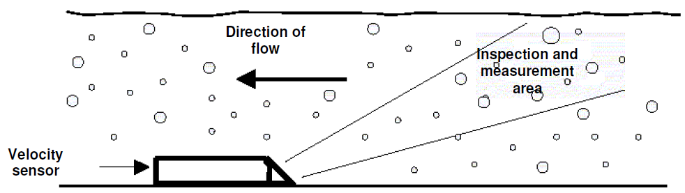
Not many vendors provide this sensor. I search on the internet, that moment I only find Mainstream Measurement. It sells variety product of sensor in immersed water.
The velocity sensor is designed to operate immersed in the liquid and is installed at the bottom of the channel where the measurements are to be taken. Below are photos during the installation of velocity sensor immersed in water.
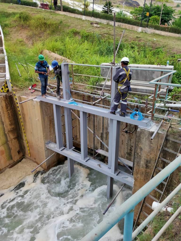
We finally complete the project. Thank you for all the team who participate in this project especially my colleague construction engineer (Mr.Chris) who design the structure to hold the immersed velocity sensor. It was critical to complete this project.
VI. REFERENCE
[1]. Spitzer, D.W., ed. 1991. Flow Measurement.
[2]. https://www.openchannelflow.com/flumes/cutthroat-flumes

One reply on “SOLVING OPEN CHANNEL FLOW METER PROBLEMS”
Your commitment and enthusiasm shine through in every section. It’s remarkable.
SukaSuka