I. INTRODUCTION
Business upstream facilities are focusing on exploration. In offshore exploration, there are platforms to evaluate the well performance and guard the safety shutdown of a wellhead.
Offshore platforms have been fabricated to accommodate specific well effluent at the first stage – preliminary treatment before sent to onshore or processing facilities to meet the gas parameters and properties based on the initial contract agreement.
Nowadays, offshore platforms could be monitored remotely. Each un-manned offshore platform is connected to form networking as wide area networks. It is similar to Headquarter inter-networking to the branch office. The network type between offshore platforms is a wide area network (WAN). The offshore platform is geographically dispersed. It requires high-speed circuits leased from a telecommunication provider to facilitate connectivity data transactions between platforms.
The physical network between offshore and onshore platforms is using radio use a broadband wireless network. Thus technology radio, networking and Internet Protocol (IP) routing eliminate barrier data monitoring.
The Integrated Control Safety System depends on the required safety and process. Typically Integrated Control Safety System (ICSS) in offshore platform comprises
- Human Machine Interface (HMI)
- Process Control System
- Safety Shutdown System
- Fire and Gas System
- The 3rd party devices such as MPFM, sand monitoring, etc.
In the Company network, the network will be divided into two data networks i.e., Enterprise network (Office Data System) and Industrial Information System. Each company has different policies and rule to define segregation between industrial network and business network. The Enterprise network will interface to the office company. The segregation adheres to Open System Interconnect (OSI) Model. Based on the OSI model, to support the offshore remote platform application such as Industrial protocol, Office, and Audio/Visual it would use at least 2 routers. To segregate between router, local PCS router, and Firewall before it passes to the Office router.
The enterprise network is logically segregated from the industrial network.
The complexity of telecom facilities depends on the requirement of the User. It means business network and industrial network is exists. Department to handle business and industrial is slightly different. Certain offshore platforms Voice over (VOIP) phone including could send an email and use office application. Often unmanned offshore platform is equipped with CCTV.
II. BACKGROUND
Modification on an existing platform which is often called brownfield projects requires a holistic understanding of the existing control philosophy. The understanding is expressed and translated to document feasibility or adequacy studies. In, early-stage identifying options and methods are responsible for every discipline engineer. Each option will have a different impact and intertwined with other disciplines. That is why the pre-FEED (Front End Engineering Detail) is conducted in the early stage. In the pre-FEED study, the engineers must closely work with the other discipline to identify options or methods that could optimize the modification.
The project follows the existing system. In an example of modification because of additional process facilities, skid comprises a unit control panel for instrumentation package. Integration require adapting to the existing system such as topology system network, power actuation (hydraulic or pneumatic), and safety shutdown system.
This technical article of the case study shows the idea of regular basis task for IT team, would bring high advantage to reduce cost in the development project.
If we are using the existing system philosophy network topology, the IT team mostly will not involve in the project. As in a typical company organization, all related to networking is usually it is under the IT department. Thus any idea related to inter-networking should initiate from instrument & control discipline engineer.
Therefore, it will evoke IT team involvement. Instrument and control systems should have basic knowledge of networking. If we did not request it the IT team wouldn’t aware of the project requirement. Often simple task in other discipline will bring lot advantage to other discipline.
Classification of instrumentation package units usually unique among the Company.
The identification boundary of the instrumentation package could start from dependencies of
- Junction box,
- Power source
- Skid
- Cable trays
- Power source
- Unit Control Panel Specification
III. UNIT CONTROL PANEL (UCP) INSTRUMENTATION OF PACKAGE UNITS
III. A. IDENTIFICATION PROPOSAL NEW SUBNET.
The Integrated Control and Safety System (ICSS) which monitors and guards the offshore platform is considered the ICSS supervisory. Any system supply with a unit control panel mostly will be under ICSS supervisory. The classification of the instrumentation package should be further identified by Company specification. However, full access to all package parameters shall only be possible from the Unit Control Panel (UCP).
Process control system (PCS) often as a repository for a package control system. Displays of monitoring and control presented in HMI get all the parameter information from PCS. It will then process further for alarm, trending, engineering unit scale, sequence of events.
The control room Supervisory Control and Data Acquisition (SCADA) obtain parameter data monitoring and control from the physical direct network connection to the onshore such as in star topology. However, the logical network connection between platforms for the information industrial system (SII) is ring network.
In this technical, I would like to go through one of the compressor projects in the offshore platform.
The compressor could be categorized as per independent system with a monitoring and safety system. It is connected to the existing industrial information network to perform monitoring and safety systems in form of a Unit Control Panel.
Identification option based on logical network and subnet, with the addition of a new instrumentation package complete with Unit Control Panel, therefore, there are two options:
- Option 1, UCP connected to a local network with the same subnet. The option 1 could be breakdown into
- Connected to PCS, where PCS as client and new UCP as server
- Independent from PCS, it is logically connected to SCADA onshore.
- Option 2, UCP separate from a local network with different subnet. This option is valid when there is no spare host IP available.
III.A.1 Typical architecture before additional UCP in offshore platforms.

In the same subnet, the maximum host is determined by the selected class subnet.
This architecture uses a local network address. Each device has a unique IP. IP comprises:
- Classful Addressing
- Classless Addressing
The Local network addresses has the same subnet for all devices. Below are classful address. It is not used anywhere on the public internet, reserved for private LANs.
| Class | PRIVATE IP RANGE Start Address | End Address | Default Subnet Mask |
| IP Class A | 10.0.0.0 | 10.255.255.255 | 255.0.0.0 |
| IP Class B | 172.16.0.0 | 172.31.255.255 | 255.255.0.0 |
| IP Class C | 192.168.0.0 | 192.168.255.255 | 255.255.255.0 |
Example of Class B Network Mask
| Netwwork Bits | Subnet Mask | Number of Subnet | Number of Hosts |
| /16 | 255.255.0.0 | 0 | 65534 |
| /17 | 255.255.128.0 | 2 | 32766 |
| /18 | 255.255.192.0 | 4 | 16832 |
| /19 | 255.255.224.0 | 8 | 8190 |
| /20 | 255.255.240.0 | 16 | 4094 |
| /21 | 255.255.248.0 | 32 | 2046 |
| /22 | 255.255.252.0 | 64 | 1022 |
| /23 | 255.255.254.0 | 128 | 510 |
| /24 | 255.255.255.0 | 256 | 254 |
| /25 | 255.255.255.128 | 512 | 126 |
| /26 | 255.255.255.192 | 1024 | 62 |
| /27 | 255.255.255.224 | 2048 | 30 |
| /28 | 255.255.255.240 | 4096 | 14 |
| /29 | 255.255.255.248 | 8192 | 6 |
| /30 | 255.255.255.252 | 16384 | 2 |
How many devices could in one local network?
The answer is based on the host portion defined by the subnet mask.
Combination of IP address and subnet mask will determine
- Network Address.
Identifies local network
- Host Address
Identifies unique devices on a network.
- Broadcast Address
Only able to broadcast on the network.
A maximum number of the host IP address will be substracted by broadcast and network addresses.
Below are illustrations Network portion and Host Portion using IP Class B. The different network portion will result in the 2 devices could not communicate
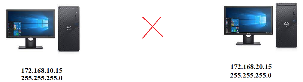

After changing the subnet mask, the 2 device will turn into one network
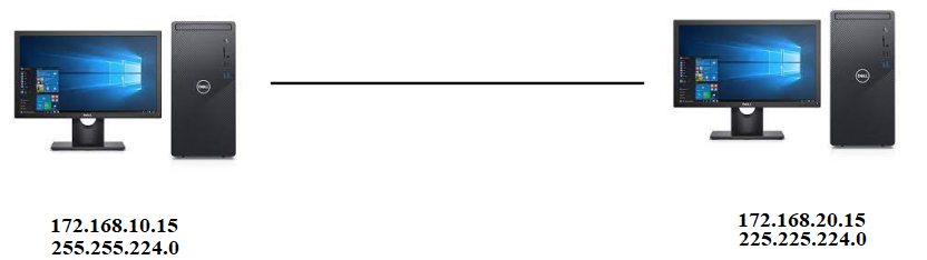

The two devices should be in the same local network if the network portion is different it will not connect. Either changing the IP or subnet mask to obtain the same network portion.
Changing the subnet will enable the IP group in one host portion. The most practical work will use different IP in the same class with the same subnet mask. This is the most selected.
III.A.2 IP and subnet mask
Most on one platform deploy using IP Class B and IP Class C. IP Class B have more addresses per network than IP Class C. Between routers could use IP Class A.
Before we go further, why do all platforms are not connected to the same network? In practice, each platforms has dedicated PCS routers. Each platform has its network.
The SCADA system in this example Experion R210B has a maximum of 100 controllers (RTU’s). Why does it need to create a subnet if the SCADA could accommodate all controllers in each platform?
So, what happens to a large network with no subnets? Every computer would see broadcast packets from all the computers and servers on the network, resulting in the switches having to move all that traffic to the appropriate ports. This leads to increased congestion, reduced network performance, and slower response times.
- Improve network performance and speed
- Reduce network congestion
- Boost network security
- Control network growth
- Ease administration
source: https://www.networkcomputing.com/data-centers/5-subnetting-benefits
The SCADA system on onshore and offshore PLCs is deploy using IP Private address.
The private IP address of a system is the IP address that is used to communicate within the offshore platform. Using private IP data or information can be sent or received within the same network.
The public IP address of a system is the IP address that is used to communicate outside the network. The public IP address is assigned by the ISP (Internet Service Provider).
III.A.2.a. Physical Connection schematic of new UCP.
The logical connection will comprise of :
- PCS as a client while unit control panels as server
- Independent from PCS and direct connection to DCS/SCADA on onshore. If the host number still could accommodate new UCP it will use the local network (same subnet) unless the spare host number is not available, it should create a new subnet for a unit.
Both have advantages and disadvantages. It is engineer judgment to choose the best requirement although certain Company has dictated preference on the Company Specification.
III. A.2.b.1. INDEPENDENCY.
Independencies UCP network by means the logical network of UCP is connected directly to SCADA instead of PCS
Besides the advantage and disadvantage, since it will separate the network. It should perform other assessments of the new system is independencies between two systems. The safety shutdown between two systems could be performed by using hardware.
This is not an exhaustive comparison, only based on the writer knowledge and experience.
- Do exchange data occurred between the two systems. For example, if some equations or calculations that require data from one system to another.
- Do PCS controlled data UCP?
| Item | Same Subnet Mask | Different Subnet |
| Advantage | – It doesn’t require additional configuration on the existing network. – It will not involve any IT department. Doing this hidden cost. It implied high-cost engineering. | – Enable to form typicality address. Data exchange table between LLP compressor and DCS onshore. – Don’t interfere with PCS, so it will not add consume any memories to the PCS – Reduce man-hours Reduce repetitive document such as data exchange table |
| Disadvantage | -Difficult to create typicality. Each platform will be a unique address for the data exchange table | – Possibility to add a new router as a consequence HMI will connect to the new subnet mask. |
IV. NETWORK
IV.1. ROUTER
The purpose of a router is to route a device/station to a different network, which is forwarding traffic to its destination based on its Layer 3 network address.
A router uses information contained in the internet protocol header to make various decisions; these decisions include
- Path determination
- Routing decision
- Load balancing
Source: https://www.section.io/engineering-education/understanding-static-dynamic-routing/
IV. 2. ROUTER INTERFACE
There are several selections of router interface. The interface connection is connected between two different networks
- Serial, The router has 2 WAN slots that can host a single-port serial module or multimode 3G module and support the following combination
- Ethernet, RJ-45 Port
- Fast Ethernet,RJ-45 Port
- Giga Ethernet, SFP Port
Cisco 2621XM wired router allows you to join wireless devices through its WIC slots, which expands its functionality. This wired router comes with two Ethernet ports, one network module slot, and two WIC slots. Its built-in Ethernet card, on of the Example NM-2FE2W Module provides two Fast-Ethernet interfaces for use with copper media, in addition to two Wan Interface Card expansion slots. Ideal for a wide range of LAN applications, the Fast Ethernet network modules support many internetworking features and standards.
Cisco Packet Router is one of simulation tools contain information various module interface.
IV. 3. DIFFERENTIATING ROUTER APPLICATION
An industrial information system network is deployed using a protocol such as modbus TCP, EthernetIP, or Profinet. ModbusTCP, EthernetIP, and Profinet will have different OSI Layer Models. However, the industrial information system network is using the same router.
OSI Layer Model consists of:
- Physical – Layer 1
- Link Layer, consist of Header and Body – Layer 2
- Network layer – Layer 3
- Transport layer – Layer 4
- Session – Layer 5
- Presentation – Layer 6
- Application – Layer 7
In offshore platforms, a minimum router is 2 router.
Router PCS
Router assign for Telecom, such as CCTV and VOIP. It has a different OSI layer model
- Application Layer Protocols
- Data Transfer Protocols for email
- Audio/Visual Protocols for CCTV
a specific network protocol is being used to manage and transfer the data.
The destination port number is in the segment header. Transport Layer 4
| Application Port | Port Number |
| HTTP | 80 |
| HTTPs | 443 |
| FTP | 20, 21 |
| SSH | 22 |
| Telnet | 23 |
| Modbus TCP | 502 |
IV. 4. Network Topology
Network Topology is using a token ring network. The ring network is selected to increase the availability. Different companies have different regulations. Certain companies decide to shut down (no-man)platform within 24 hours. If this period the maintenance could not Lose network could mean shutdown in 24 hours.
IV. 5. IP Routing
A router opens the IP packet to read the destination address, calculate the best route, and then send the packet to the final destination, and if the destination is in a local network, it sends the packet directly to the receiving computer.
IP routing is expressed in router. There 2 router consists of:
- PCS Router
- Office Router
Most likely by design among offshore platforms will form ring network topology form in synchronous digital hierarchy backbone network to increase the availability. However, network topology between onshore and offshore having a physical star topology network through point-to-point wireless and ethernet radio. A point-to-point network is a common method for connecting a remote site to another site.
Below are the PCS router network before the modification
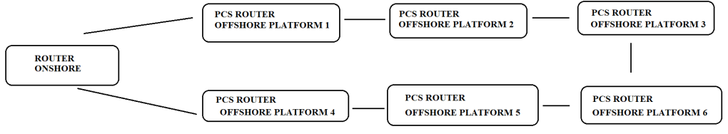
Each offshore platform is the host network. So if you have 8 platforms then you have 8 host networks.
With, a new subnet mask in the same platform it means the new device will be a new host. Data exchange between two systems to demonstrate a level of independencies between two systems.
IV.6. Interconnection logic network
This modification will perform in each routing table on the router both on the onshore and offshore platforms. Below is an illustration that adding a new subnet will reduce the cost of the man-hour project.

Routes are used to determine where the IP packet is sent to a router on the network. The interfaces on the router write the network addresses that are connected to them in their routing table. Therefore, the router decides where the IP packet will go according to the records in the routing table. A static router is manually configured to define the path, therefore whether new subnet or new IP in the same subnet, each router should be configured to define the path.
There are 3 types of routing:
- Static routing, Static routes are user-defined routes that cause packets moving between a source and destination to take a specified path. Static routes provide fixed routing paths through the network. They are manually configured on the router. If the network topology changes, the static route must be updated with a new route. Static routes are private routes unless they are redistributed by a routing protocol.
- Default routing, also known as gateways of last resort, are used to route packets that are addressed to networks not explicitly listed in the routing table
- Dynamic routing, In dynamic routing, the network protocol adjusts the path automatically, based on network traffic or topology. Changes in dynamic routes are shared with other routers in the network
The router could be configured default, static or dynamic. Mostly offshore platforms will utilized combination of static and dynamic. The selection is based on several judgments and conditions. The ring network between offshore platforms is using static routing., static routing is commonly deployed. In terms number of offshore platforms, it is not a large network. Static routing is a process in which we have to manually add routes in the routing table, therefore no bandwidth usage between routers. It adds security because the only administrator can allow routing to particular networks only.
Dynamic routing tables created using routing protocols. These protocols are used to communicate between routers proving the information about the most efficient way to route data.
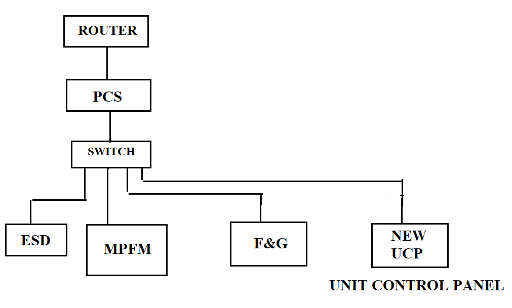
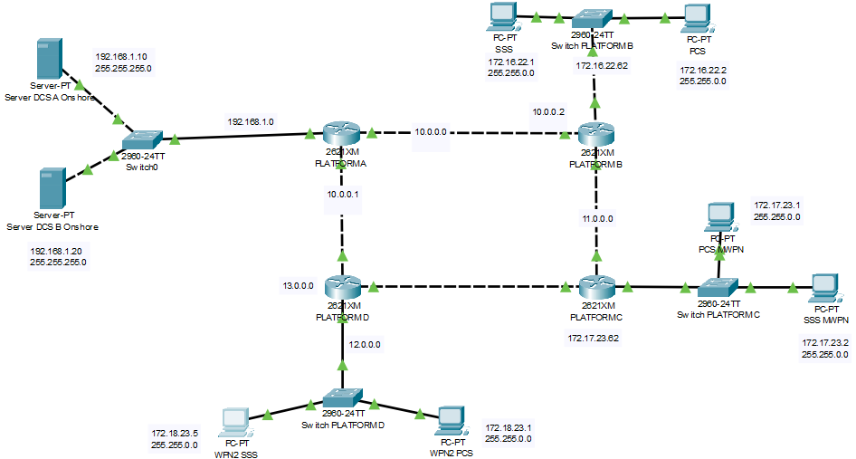
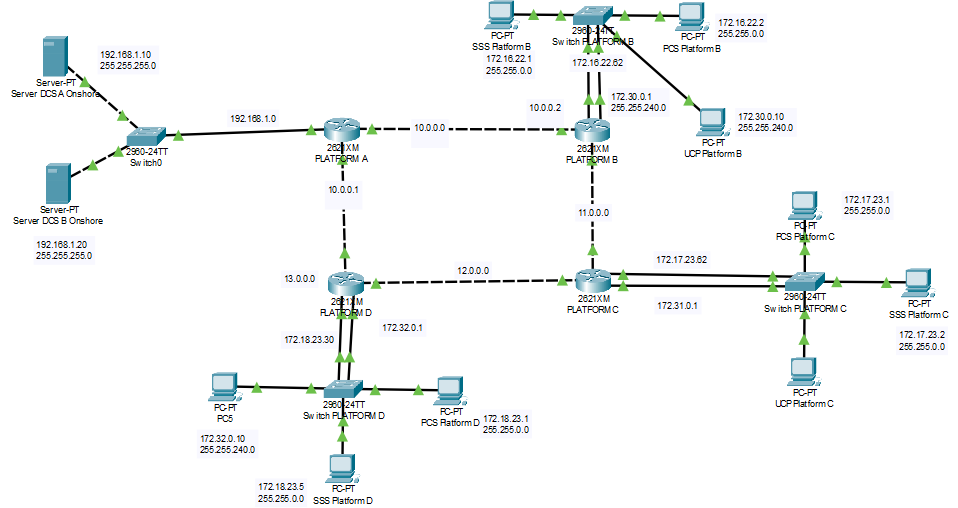
Below is an illustration of an existing ICSS network. The logical network is configured manually in each router to define the path
IV.7. STATIC ROUTES
This study case uses a static router. The background reason for using the static routes is suitable for static compare to dynamic.
When to use static routes
Static route can be used to:
- Reduce the number of routes advertised by a router.
- Create a backup route if the primary route fails.
- To connect a device to a specific network
- To connect a stub router or a stub network.
Advantages of static routing
- It provides easy routing table maintenance in networks.
- Static routing consumes less bandwidth when compared to dynamic routing as no CPU cycles are used in route calculation and communication.
- Because static routes do not advertise their route over the network, it results in better network security.
Limitations of static routing
- In large networks, configuring and adding a static route to the routing table is very difficult.
- Configuring static routes requires background knowledge of the network topology by the network administrator.
- A static route is error-prone.
Below are the illustration of routing to ensure the idea is working

Below is the example of using dynamic routing
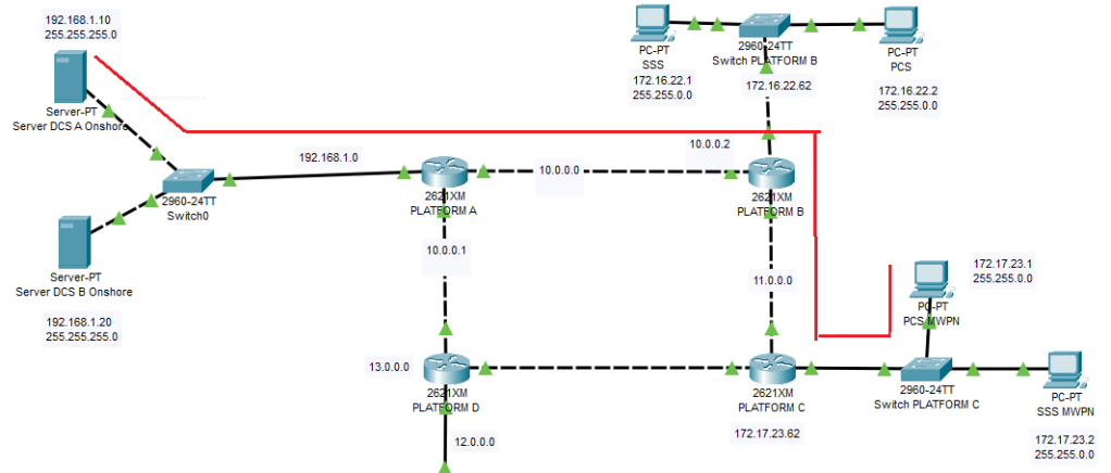

As seen the red highlight routing, to create connection from Server DCS A onshore to PCS Platform C, the router .
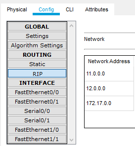
Routing Information Protocol (RIP) is a commonly used routing protocol in small to medium TCP/IP networks. It is stable protocol that uses a distance-vector algorithm to calculate routes.
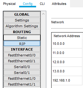
RIP declare on the router Platform A
the network related to the path
192.168.1.0
10.0.0.0
11.0.0.0
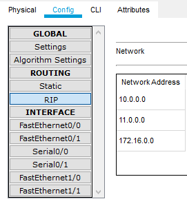
RIP declare on the router Platform B
the network related to the path
10.0.0.0
11.0.0.0
RIP declare on the router Platform C
the network address related to the path
11.0.0.0
172.17.0.0
Below are the illustration if using new subnet mask for the UCP. One more interface port is utilize.

IV.8. HMI to new UCP
Often a UCP has a dedicated HMI, it represents the detail of the package system. This includes start-up sequence and start-up and maintenance inhibit.
Part of the display will be copied to the HMI process platform. It is necessary since, during the start-up process, the operator has to ensure other parameter processes before running the package system. In normal operation mode, it will be used to monitor the other process and package system in stable condition.
In HMI, new IP will be added to retrieve data from UCP.
The UCP is using a new subnet mask. The connection HMI to UCP could deploy using VLAN Routing. VLAN Routing is creating a segregation connection from HMI to UCP. The additional UCP will add the server to the HMI
- Connection HMI (client) and PCS (server)
- Connection HMI (client) and UCP (server)
Inter-VLAN for HMI could be created if UCP is using new subnet mask.
V. THE COST REDUCTION
Cost reduction is due to typicality. The 3rd party system package could be typical on all platforms.
- Each platform will have a uniform P&ID including the tag
- Each 3rd system package could have the same Modbus address in all platforms cause it doesn’t depend on an available address on the PCS existing.
- In the onshore control room, DCS address could be only distinguished by the Modbus slave based on the area while the numbering order will be same.
IV. 1 Engineering document
If there are 5 offshore platforms, there are repetitive engineering work that could reduce such as
- P&ID for instrumentation package could be typical instead of each platform.
- Modbus exchange data table could be typical instead of each platform.
IV.2 Human-Machine Interface (HMI) Modification
Because of additional UCP, the local HMI shall be modified as well, the modification will include an additional page, Modbus address, and new controller.
- Display UCP could be similar on all platforms. Therefore, if HMI is identical in each platform, it will give more advantage to the man-hour.
- Modbus address order could be the same/similar for UCP in all platforms.
IV.3 Process Control System
Since SCADA onshore has a direct network connection to the unit control panel, therefore, no major interference with PCS. It will not consume memory.
IV.4 SCADA
As they do not connect it to the PCS router, the address for retrieve information could be in the same order on each platform. The addressing could be the same, the difference only the IP for each platform.
By doing this, the only difference is the area numbering usually found on the front of the tag name.
in example 11-PT-001, 12-PT-001, and 13-PT-001
- 11 = Area A
- 12 = Area B
- 13 = Area C
VI. CONCLUSIONS
The magnitude cost of reduction is not presented in this article. This is a study case to reduce the cost that this modification could reduce labor force, repetition document during basic engineering but the writer could not exactly quantify the magnitude cost reduction.
Different Companies may use a unique approach. Discussion with technical authority Company. It required a project management team to achieve the goals.
REFERENCE
The Best Damn Cisco Internetworking
https://www.cisco.com/c/en/us/td/docs/routers/access/800M/software/800MSCG/routconf.html#24575

One reply on “How Changing Logical Topology Reduce Project Cost (Control System Discipline)”
I appreciate how you demystify complex concepts into comprehensible chunks. Well done!
SukaSuka